Umber Networks · Technical Architecture
Umber Fi-Wi: The 802.11 Forwarding Plane
Centralized packet memory, scheduling, and radio-resource control over distributed radio heads
Companion presentation: Why 802.11 Needs a Forwarding Plane, and Where DPDK Fits, presented by Robert McMahon at the DPDK Summit in Stockholm.
Abstract§
The end-to-end goal of networking is simple to state: copy a message from the memory of one machine to the memory of another. Every layer between is an implementation of that copy, and each layer re-quantizes it into its medium's natural unit(s).
The wired legs of that copy received their forwarding planes decades ago: an Ethernet switch maps 802.3 frames to ports, and an IP router maps L3 IP-addressed packets to next hops and rewrites their L2 MAC headers to transit those hops. Wi-Fi has sophisticated radios, sophisticated modulation, and increasingly sophisticated mechanisms for coordinating transmissions. What the wireless leg still lacks is its structural equivalent: an infrastructure forwarding plane that centralizes packet and RF state and schedules transmissions using distributed radio resources across electromagnetic fields within a shared spacetime domain.
Fi-Wi introduces that function for 802.11: it maps queued wireless work to a radio and a scheduled service opportunity. Conceptually:
queued wireless work + distributed PHY observations of the RF field → concentrator-allocated service on a selected radio resource (RRH or RRH array)
The scheduled resource may include a radio head or radio-head array, a channel or resource unit, a transmission opportunity, an aggregation budget, and, where the radio exposes the necessary control surfaces, rate and spatial-stream policy.
Fi-Wi implements this function in a central concentrator connected over fiber to distributed Remote Radio Heads (RRHs). Packet memory, queue state, scheduling state, radio observations, transmission outcomes, and policy are brought into one execution domain. The RRHs remain standard 802.11 transmitters at the air interface while moving as much infrastructure-side decision making as commodity Wi-Fi silicon permits into the concentrator. Where endpoint behavior can be influenced or made cooperative, the same scheduler can extend service allocation toward clients through induced transport shaping or explicit network-to-endpoint grants, without changing the 802.11 medium-access rules.
External transmitters, legacy clients, listen-before-talk requirements, random backoff, propagation, fading, and interference remain physical realities. Fi-Wi does not turn unlicensed spectrum into a contention-free cellular channel. It changes which parts of the problem are left to independent local decisions: within the Fi-Wi control domain, packet placement and service allocation are planned globally rather than discovered independently by autonomous APs.
The central engineering hypothesis is therefore narrow and falsifiable:
For a set of radios operating over a shared and imperfectly observable wireless medium, centralized allocation using shared queue, radio, and transmission state can produce better service outcomes than independent APs making local decisions over the same medium, provided the benefit of coordination exceeds the latency and error introduced by centralization.
Everything else in the architecture follows from that proposition.
Low Latency, Low Loss, Scalable Throughput (L4S) is integral to Fi-Wi: the forwarding plane controls the wireless service process, and L4S closes the congestion-control loop around it. The same forwarding plane also enables interference-aware scheduling, improved aggregation, airtime accounting, observability, mobility, and future learning systems, and is the precondition for dynamic point selection, which section 10.1 gates on station-state ownership.
Fi-Wi replaces an architecture built from autonomous APs with a wireless fabric in which distributed radio resources share centralized packet state, RF state, and scheduling.
1. The Missing Layer in Wi-Fi§
1.1 Networking repeatedly moves contention into a forwarding plane§
Early Ethernet was a shared medium on which stations contended for access to a common bus. Modern Ethernet preserves that protocol lineage, but switched Ethernet changed the architecture: frames are no longer delivered by every attached station competing on one shared wire. A switch learns where destinations are and forwards each frame toward an appropriate port. IP made a different transformation, maintaining forwarding state that maps a packet's destination to a next-hop resource. Neither forwarding plane eliminates the uncertainty of the underlying network. Each moves an important decision from distributed endpoint behavior into infrastructure that has the state required to make that decision well.
Modern Wi-Fi has never completed the equivalent transition. A conventional deployment consists primarily of autonomous MACs: each AP has its own packet queues, observes its own channel, runs its own rate adaptation, holds its own aggregation state, performs its own medium access, reacts to retries and interference locally, has incomplete knowledge of neighboring AP demand, and commits packets into local radio queues before the eventual service time of those packets is known. Controllers and cloud management coordinate configuration, channel plans, roaming policy, and security, but these are slow-path functions. They do not own the real-time queueing and transmission decisions that create the wireless bottleneck.
Fi-Wi moves that boundary.
1.2 What "forwarding" means in Fi-Wi§
The word forwarding is used here structurally, not as a claim that Fi-Wi performs IP-style topology computation. There is no wireless equivalent of recursive IP reachability in this architecture. The analogy is the mapping function. An IP forwarding plane performs approximately destination prefix → next hop; an Ethernet bridge performs approximately destination MAC → output port. An IP router maps L3 IP-addressed packets to next hops and rewrites their L2 MAC headers for transit across those hops. The Fi-Wi forwarding plane performs approximately:
queued wireless work + distributed PHY observations of the RF field → concentrator-allocated service on a selected radio resource (RRH or RRH array)
A more explicit representation is:
(STA, TID, queued MPDUs, policy, observed radio state) → (eligible radio resource, service opportunity, transmission policy)
The eligible radio resource may be a single RRH or, where the required synchronization and PHY control are available, an RRH array.
The output may specify the RRH, the channel or frequency resource, the eligible transmission window, a TXOP budget, an aggregation policy, traffic-class treatment, and, where exposed by the chipset, MCS and spatial-stream policy. The A-MPDU transmitted by the RRH is therefore the physical unit of work produced by a broader forwarding and scheduling decision.
The distinction matters because the fundamental Fi-Wi invention is central ownership of the state required to decide how the wireless resource should serve the queued work. Packet tunneling to a remote radio already exists; ownership of the decision state is what has been missing.
1.3 Routers, switches, and the concentrator compared§
The analogy to routers and switches is load-bearing in this document, so its limits deserve precision. The three forwarding planes of Figure 1 solved different problems with different instruments, and the concentrator is not simply either predecessor applied to radio.
The Ethernet switch abolished its shared medium rather than scheduling it. Bridging turned one contended wire into N dedicated point-to-point links; contention moved from the medium into the switch fabric, where silicon arbitration resolved it. The switch's state is flat and reactive: a learned table mapping identity to port, aged in minutes, flooding on a miss. It is invisible to endpoints, and it needs no notion of time.
The router introduced structure instead of dedication. Its addresses encode location, so its state aggregates: forwarding tables grow with topology rather than population, and a control plane of distributed protocols computes them. The router terminates frames so that dissimilar media can internetwork, and it contains the broadcast domain, but it still assumes the link below it delivers. Forwarding lookup and link scheduling remain separable functions.
The concentrator faces the case neither predecessor faced: a medium that cannot be dedicated and does not reliably deliver. Spectrum cannot be switched into point-to-point links, so contention cannot be abolished, only planned. The concentrator therefore keeps state neither predecessor kept: per-station service history, airtime debt, retry and channel observations, and clock relationships, with a half-life measured in milliseconds where a MAC table ages in minutes and a route persists for hours. Its forwarding decision binds work to a location and a time under a policy, which is why forwarding and scheduling share one state domain (Section 6.2). Its forwarding semantics therefore require a synchronized timebase as part of correctness rather than merely as a management convenience. The unit of work differs as well, an axis developed in Section 1.4.
| Axis | Ethernet switch | IP router | Fi-Wi concentrator |
|---|---|---|---|
| Strategy against sharing | Abolish the shared medium | Structure, aggregate, contain | Schedule what cannot be abolished |
| Unit of work | 802.3 frame | Packet | Aggregate (A-MPDU) within a TXOP |
| Forwarding state | Flat learned identity → port | Hierarchical prefix → next hop | Work → (RRH, opportunity, policy) |
| State half-life | Minutes | Minutes to hours | Milliseconds |
| Time requirement | None | None | Shared timebase as a correctness requirement |
| Endpoint visibility | Invisible | Explicit gateway | Invisible to legacy clients; explicit peer to cooperating clients |
| Resource-domain effect | Contains collisions | Contains broadcasts; aggregates forwarding state | Coordinates managed contention |
Two nuances keep the comparison honest. First, scheduled forwarding is not unprecedented: time-sensitive networking gave Ethernet gate-scheduled egress, and deterministic networking extends the idea at L3. Those systems schedule links the network owns end to end. The concentrator extends scheduled forwarding to a medium the network does not own, shared with transmitters it cannot command, which is why its grants are eligibility decisions rather than commands (Section 7.3). Second, the concentrator combines the postures of both predecessors toward endpoints: like a bridge, it is invisible to unmodified clients; like a router, it can be an explicit peer to endpoints that opt in, through the ClientGrants of Section 9.3.
The containment lineage then reads cleanly. The switch contained collisions. The router and its subnets contained broadcasts and let forwarding state aggregate. The concentrator coordinates contention among the transmitters in its scheduling domain, the boundary inside which use of the shared resource is planned rather than independently pursued. Unmanaged transmitters remain outside that boundary. One analog remains deliberately unclaimed: routing eventually required BGP to coordinate independent domains, and coordination between adjacent scheduling domains is similarly open, acknowledged here as frontier rather than feature.
The comparison also has a deployment consequence. The concentrator takes over much of what the switched building did: radio heads attach to it over fiber as PCIe endpoints of its I/O domain rather than to closet switches over Ethernet, so the access ports and the bridging that used to fan out to autonomous APs move inside the concentrator. Traffic between two wireless stations it serves becomes a memory operation rather than a round trip through a switch fabric. Mobility decides what survives the contraction: stationary objects stay switched, and objects that move use wireless. Ethernet keeps the fixed plant, the uplink toward the router stays, and power is delivered at the head, since fiber carries the device relationship and not the supply. The two planes divide the building by what moves rather than competing for the same endpoints.
1.4 Units of work: the network as a distributed memory copy§
The goal that opened this document, copy a message from one machine's memory to another's, deserves development, because every layer's unit of work is a consequence of it. An application calls write() on one host and read() on another, and everything between those two calls is the implementation of a distributed memory copy. The goal survives every layer; each re-quantizes the copy into the unit its medium charges for, or the unit its decision requires.
| System | Unit of work | What determines the unit |
|---|---|---|
| Application | Message | The object the user actually experiences; the copy's natural unit |
| TCP stack | Window of MSS-sized segments | Flow and congestion control; per-segment reliability accounting for the copy |
| IP router | Packet | The forwarding decision across heterogeneous media |
| Ethernet switch | 802.3 frame | Movement across a dedicated link, where every frame costs about the same |
| Fi-Wi concentrator | A-MPDU within a TXOP | A transmission on the air, whose cost is dominated by fixed overhead (preamble, interframe spacing, arbitration) |
The escalation is not arbitrary. A dedicated wire charges almost nothing extra per frame, so the switch's unit can stay small. The router's unit is the decision itself. The air charges per transmission, with overheads that dwarf small payloads, so the concentrator's efficient unit is the batch: the aggregate within a TXOP. A transport-window delta, an A-MPDU, and a TXOP budget are successive control representations of the same underlying transfer, expressed in the native units of transport, MAC aggregation, and airtime. The uplink mechanisms of Section 9.3 exploit that alignment directly.
The wired portion of the copy converged on memory semantics decades ago: a NIC moves bytes by DMA, zero-copy stacks remove the intermediate copies, and RDMA makes remote memory an explicit programming model. Inside the Fi-Wi system the fronthaul is literally a memory bus, PCIe extended over fiber, with each radio a DMA endpoint of concentrator packet memory. The air is the last leg of the copy that is not memory-like: it is shared, lossy, time-varying, and priced per transmission rather than per byte. This final leg therefore adds link-local retransmission, aggregation, contention management, and radio-resource scheduling beneath the end-to-end transport controls.
Stated in this vocabulary, Fi-Wi's goal is compact: treat the building as one distributed memory system and schedule its most expensive bus. The concentrator holds the message's bytes in one memory; ServiceGrants decide when, and through which radio, each piece of the final copy executes. The simplification is deliberate and bounded: the air is not a bus and cannot be made one, which is why the copy's last leg is scheduled rather than merely clocked, and why the claim discipline of Section 19 governs everything said about it.
2. Why the Autonomous AP Became the Limiting Architectural Unit§
Wi-Fi's distributed MAC was an extraordinary engineering success: it allowed independently manufactured devices to share unlicensed spectrum without a central spectrum authority. That strength also created a limitation, because each autonomous AP optimizes from a local view.
Consider two nearby APs serving two clients. Each AP can observe some combination of its own queue occupancy, received signal strength, local CCA state, local retries, local rate estimates, associated-station state, and perhaps limited neighbor information. Neither AP owns the other's queued demand, transmission deadlines, aggregation opportunities, retry history, or service deficit, and neither owns the operator's global objective across both cells. The two APs are not solving one scheduling problem; they are solving two local problems whose solutions interact through RF.
As density increases, this distinction becomes decisive. A locally rational decision can be globally poor. Raising MCS may increase retries in another cell. Extending a TXOP may improve local efficiency while increasing another station's service delay. Wide channels may maximize an individual PHY rate while reducing reuse across a floor. Queues can build at one radio while another usable radio resource sits idle nearby.
The issue is not that autonomous algorithms are badly designed. The issue is that their state vectors and objective functions are local by construction. Fi-Wi changes the state boundary.
3. Why Enterprise WLAN Controllers Did Not Already Solve This§
Enterprise WLANs already attempted centralization. The lightweight-AP and controller era moved significant functionality from individual APs into centralized systems: policy, configuration, mobility, security, and portions of forwarding. But the split stopped above much of the timing-critical MAC, and that outcome was rational for three reasons.
3.1 The transport constraint§
The installed enterprise transport was Ethernet. Ethernet is an excellent packet network, but ordinary switched backhaul is not equivalent to extending a device bus from a host to a radio. Real-time 802.11 operation includes deadlines at microsecond timescales: immediate ACK behavior, PHY interaction, listen-before-talk, backoff progression, and transmission status cannot be placed arbitrarily far across a packet network with variable queueing. The WLAN controller could centralize policy. It could not reliably behave as though every remote Wi-Fi device were locally attached hardware.
3.2 The silicon constraint§
Merchant Wi-Fi silicon was built around the autonomous AP. Rate adaptation, aggregation, retry policy, queue ownership, EDCA behavior, and other timing-sensitive MAC functions migrated into firmware, and those interfaces were never designed as open host-side scheduling APIs. An AP vendor could centralize only what the chipset allowed it to centralize.
3.3 The demand constraint§
Through much of the controller era the WAN itself was comparatively slow. When a subscriber had tens of megabits per second of Internet access and the WLAN could deliver hundreds under favorable conditions, there was little economic reason to build a far more difficult real-time forwarding architecture. The controller centralized what produced value at the time, and the remaining split point was determined by transport, silicon, and economics.
The lesson is therefore not that centralized Wi-Fi failed. The lesson is that centralization stopped above the wireless bottleneck. Fi-Wi resumes the architectural split at that boundary.
4. Why This Architecture Is Practical Now§
Three conditions have changed.
4.1 The bottleneck moved§
Multi-gigabit access networks increasingly place the limiting resource at the final wireless hop. A Wi-Fi system can be the dominant source of variable service time even when the WAN and building backbone have substantial unused capacity. Once the radio is the bottleneck, ownership of radio service becomes economically important.
4.2 Fiber can extend a device relationship over building distances§
Fi-Wi's use of fiber is architectural: the target fronthaul extends the radio device relationship so that RRHs remain peripherals of the concentrator's I/O domain. PCIe-over-fiber preserves familiar DMA and device-control semantics while moving the radio physically away from the host. Fiber provides distance; the bus-like interface preserves ownership. The result is fundamentally different from placing an independent AP behind an Ethernet link.
4.3 Host processing has become a credible forwarding platform§
Modern server CPUs provide large PCIe lane counts, high memory bandwidth, many isolated cores, hardware IOMMUs, and userspace packet-processing frameworks such as DPDK. It is now practical to dedicate host compute to functions that historically lived inside individual AP SoCs, and the economic inversion matters: rather than placing a general-purpose CPU, a full networking stack, and an independent scheduler beside every radio, the compute is concentrated in a serviceable rack environment and amortized across many RRHs.
The principal remaining execution risk is the Wi-Fi silicon control surface. Commodity radio devices were not designed for this architecture, so Fi-Wi depends on sufficiently open host interfaces, driver work, firmware cooperation, or eventually purpose-designed radio silicon. That constraint is treated explicitly as a project risk rather than hidden behind the architecture.
5. System Architecture§
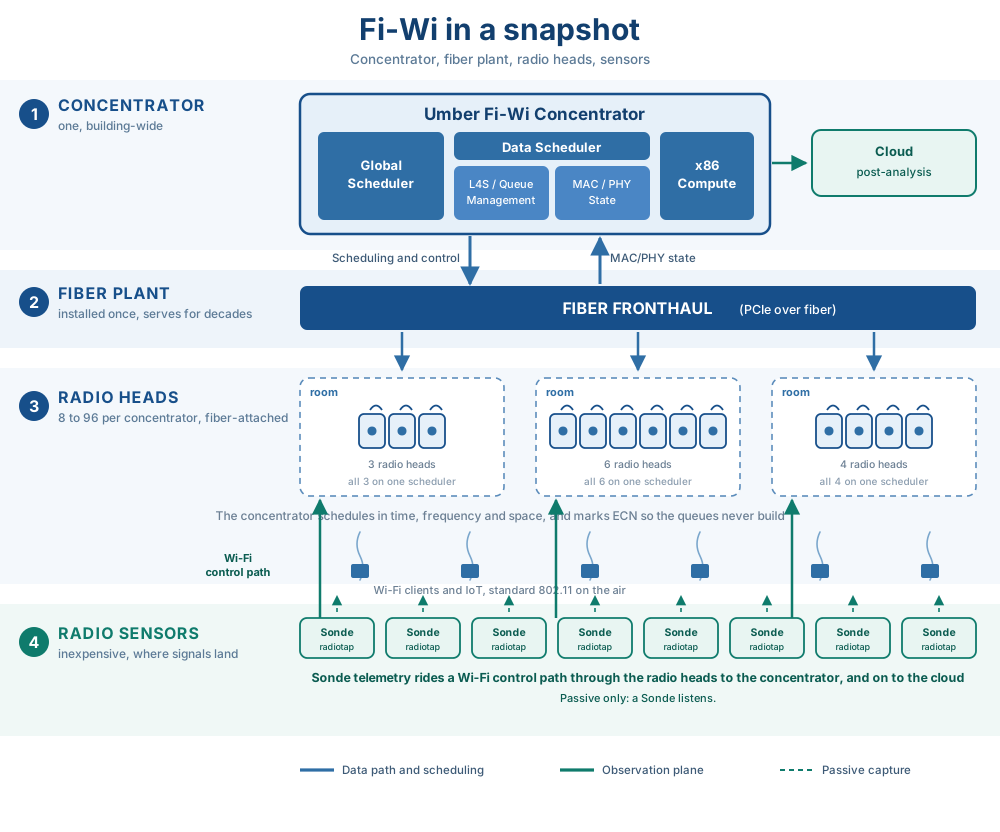
The Fi-Wi system contains four principal elements.
Concentrator. Owns packet memory, queue state, forwarding decisions, scheduler state, policy, telemetry correlation, and the host-side data path.
Fronthaul. Connects the concentrator to distributed radio devices using a low-latency, device-oriented interface over fiber.
Remote Radio Heads. Provide the 802.11 radio interface and execute the timing-critical functions that must remain adjacent to the PHY, or that commodity silicon does not yet expose to the host.
Sonde radio sensors. Abundant inexpensive sensors placed where signals land and where they originate. A Sonde listens passively rather than joining the network, and its radiotap telemetry rides a Wi-Fi control path to the radio heads, back through the fronthaul to the concentrator, and on to cloud post-analysis. Sondes therefore report the medium as it appears at the positions devices occupy rather than only at the radio heads, which supplies the scheduler and the evaluation framework with observations taken where service is consumed rather than where it is transmitted.
6. The Forwarding Plane§
6.1 Packet memory stays central as long as practical§
A conventional AP commits a packet to a radio-specific queue well before the radio gains access to the medium. That is a form of early binding: once the packet sits inside a local MAC queue, another radio may become the better choice, but the infrastructure has no clean mechanism to reclaim and redirect it. Fi-Wi keeps packets in concentrator memory until late in the scheduling process, which makes placement a decision rather than an accident of queue topology. If one RRH becomes busy, accumulates retry pressure, loses eligibility, or otherwise becomes a poor service choice, subsequent queued work remains available to another eligible RRH.
6.2 Forwarding and scheduling are coupled§
In wired networking, forwarding lookup and link scheduling can often be treated as separate functions. Wireless weakens that separation, because a radio cannot be selected sensibly without considering whether and when it can provide service. The Fi-Wi forwarding decision therefore contains a scheduling dimension. A forwarding entry is not simply STA → RRH; it is closer to work → RRH + opportunity, where the opportunity is constrained by association state, channel occupancy, radio availability, regulatory behavior, interference relationships, expected PHY efficiency, service already delivered to competing traffic, queue deadlines or weights, and other traffic scheduled in the same time and frequency region. This is why the forwarding plane and the scheduler share one state domain.
7. Scheduling a Contended Fi-Wi Network§
This is the central worked example of the architecture. Fi-Wi operates in unlicensed spectrum, so the scheduling problem is not "which transmitter will transmit at exactly time t regardless of the world?" It is: given the resources under infrastructure control, the observed state of the medium, and the requirement to coexist with unmanaged transmitters, which queued work should be made eligible for service next, through which RRH, and under what transmission policy? That distinction is foundational.
7.1 Inputs to the scheduler§
For a set of RRHs and associated stations, the concentrator can maintain a shared state vector containing some or all of the following.
Demand state: queue depth by STA and TID; packet age; flow weights; latency policy; aggregation opportunity; recent offered load.
Radio state: RRH and channel eligibility; CCA and busy observations; retry history; recent TX status; RSSI and SNR; measured PHY rate; CSI where supported; recent MCS and spatial-stream outcomes.
Resource state: channel assignment; known interference relationships; the RRH conflict graph; allowed TXOP duration; scheduled or recently consumed airtime; other grants in the scheduling horizon.
Service state: airtime delivered per station or traffic class; service deficit; retry airtime; transmission completion history; predicted service cost.
Sensed state: passive radiotap observations from Sonde sensors at the positions devices occupy: received signal, observed rates and retries, and channel occupancy as it is heard away from the radio heads. These reports travel over the air and through a radio head rather than down the fronthaul, so they carry looser timing than RRH-reported state and inform slower control decisions rather than per-TXOP ones.
The scheduler does not need perfect knowledge. It needs enough shared information for its decisions, across a distribution of operating conditions, to outperform the independent decisions it replaces.
7.2 Scheduler output§
For a selected piece of queued work, a scheduler decision produces a ServiceGrant:
ServiceGrant {
    station
    TID / service class
    RRH
    channel / resource
    TXOP budget
    aggregation budget
    eligibility time/window
    optional MCS policy
    optional NSS policy
}
The ServiceGrant is an internal object issued to infrastructure the operator owns and trusts. A separate protocol object, the ClientGrant, is defined in Section 9.3 and crosses a different trust and enforcement boundary.
The exact ServiceGrant fields depend on the control surface exposed by the radio, and a key architectural discipline is that unsupported controls must not be claimed. If the tested firmware retains rate adaptation, then the scheduler controls placement and service opportunity while the firmware chooses MCS. If host-side MCS control later becomes available, MCS becomes another scheduler output. The architecture is designed to degrade honestly with the capabilities of the radio implementation.
7.3 Local radio execution remains necessary§
The concentrator does not repeal 802.11. An RRH may still need to perform clear-channel assessment, obey listen-before-talk requirements, execute randomized backoff where required, transmit only after gaining access, process immediate ACK and BlockAck behavior, and report completion, retries, airtime, and other results. The scheduler controls what work is presented to which radio and under what policy; the radio executes the air-interface rules. This creates a useful separation. Global decision: which controlled resource should serve the work? Local execution: can that resource legally and physically transmit now?
7.4 Fi-Wi reduces self-contention; it does not claim to eliminate contention§
This language is deliberate. Fi-Wi coordinates infrastructure transmitters that would otherwise make independent decisions. It cannot prevent an unmanaged neighboring AP, a legacy client, or any other lawful unlicensed transmitter from occupying the channel, and it therefore does not promise a contention-free medium. The architectural goal is to avoid adding unnecessary infrastructure self-contention to the contention that cannot be controlled.
7.5 A possible scheduling objective§
The production scheduler need not be expressed as one global optimization problem, but the architecture can be understood this way. For each candidate ServiceGrant g, estimate the expected delivered bits, the expected airtime cost, the retry risk, the interference cost imposed on other scheduled work, the service deficit of the destination, the packet urgency, and the confidence in each estimate. Then select a feasible set of grants that maximizes a policy objective such as:
utility = Sum over g of [ w_g * E(delivered_bits_g) + lambda*D_g - mu*I_g - nu*R_g ]where w_g is the policy or service weight, D_g is accumulated service or airtime debt, I_g is the expected interference cost, and R_g is retry or uncertainty risk, subject to constraints including radio availability, station association, regulatory requirements, conflict relationships, TXOP bounds, hardware capabilities, and resource eligibility.
This formulation is illustrative, not a commitment to one implementation algorithm. The architectural point is that every term can be evaluated in one place. Independent APs cannot optimize the same global objective when the required state is divided among them.
8. The Two-RRH Example§
The minimum useful example is two radio heads serving two stations.
Let H_A represent the useful radio channel for cell A, H_B the useful radio channel for cell B, and H_x the coupling between the two cells. When H_x is small, simultaneous or closely spaced service has low interaction cost. As H_x rises, decisions in one cell increasingly affect the other. Two independent APs observe this interaction after it occurs and adapt locally. The Fi-Wi concentrator observes both service histories and makes a joint allocation decision before presenting new work to either radio.
This yields a direct experimental question: as cross-cell coupling increases, does centralized scheduling degrade more gracefully than independent local scheduling? That question is measurable, and it is capable of proving the architecture wrong. If independent APs perform as well or better across the operating region, the claimed coordination advantage has not been demonstrated. That falsifiability is a feature, not a weakness.
9. Uplink: What the Infrastructure Can and Cannot Schedule§
Downlink and uplink control are not symmetric. The infrastructure owns the downlink queues; it does not own the queues inside arbitrary client devices. Fi-Wi therefore describes uplink control as a progression rather than claiming universal deterministic scheduling: MAC-layer scheduled access for capable radios (9.1), indirect benefit for unmodified clients (9.2), and network-to-endpoint scheduling above the MAC (9.3).
9.1 Scheduled uplink mechanisms§
Modern 802.11 includes mechanisms such as trigger-based uplink operation that allow an AP to allocate uplink resources to participating stations. Within such an opportunity, associated stations are explicitly scheduled rather than independently competing for that transmission opportunity, which improves the infrastructure's ability to coordinate capable clients.
The AP must still acquire the medium, and normal client contention continues outside the scheduled opportunity; scheduled access narrows a station's EDCA autonomy rather than removing it. RFC 9913 (Reliable and Available Wireless Technologies, Informational) describes trigger-based access as centralized scheduling that can remove contention among participating associated stations for those uplink transmissions while preserving listen-before-talk for medium acquisition.
9.2 Legacy and uncooperative stations§
Legacy clients continue to use standard contention behavior. Fi-Wi still benefits them indirectly through reduced infrastructure self-contention, deliberate downlink scheduling, queue management, radio placement, channel planning, admission policy, association incentives, and lower contention pressure from the traffic the infrastructure does control.
The architecture therefore never depends on universal client modification. Better client cooperation expands the control surface; it is not a prerequisite for the forwarding plane to exist.
9.3 Network-to-endpoint scheduling above the MAC§
Between MAC-layer scheduled access and passive legacy benefit sits a third class of uplink control. It requires no new client silicon, and it operates at two capability levels that must be kept distinct.
Unmodified endpoints: induced shaping. Fi-Wi cannot command an ordinary TCP sender's MAC transmission time. For TCP uplink flows whose return path traverses the concentrator, the design can influence when traffic is released toward the wireless bottleneck. Advertised receive-window control and ACK release timing can shape when the sender's own transport releases work, while the timing of downlink bursts can influence the client's reflexive ACK traffic. This is scheduling influence rather than grant obedience: the network shapes offered load so that endpoint demand better aligns with predicted wireless service. It reaches the same unmodified population as Section 9.2. Its granularity is millisecond-scale, its release edges must be deliberately dithered, and traffic no transport mechanism can gate (ARP, DHCP, management frames, keepalives) sets a floor on what it consolidates.
Cooperative endpoints: explicit ClientGrants. The design allows a cooperating endpoint library to accept network-issued transmission grants, ClientGrants, expressed as eligibility windows against the shared TSF-affined timebase of Section 11, with per-packet access telemetry returning each client's measured medium-access experience. This would move beyond indirect shaping: the endpoint would defer application and transport release until the granted service interval. The Wi-Fi MAC would still perform the required 802.11 medium-access procedure; the grant controls when work is made eligible, not whether the station may ignore listen-before-talk. The proposed userspace library would provide the release timing without requiring kernel, driver, or radio changes. Participation would be opt-in, and a non-participating client would lose nothing relative to Section 9.2.
The ClientGrant and the ServiceGrant of Section 7.2 would emerge from the same scheduler but remain different objects. A ServiceGrant is issued to infrastructure the operator owns. A ClientGrant is an advisory eligibility decision issued to an independently administered endpoint; the design therefore measures each client's actual grant-to-air behavior rather than trusting declared capability and sizes guard intervals from those observations.
This mechanism class is Design / pre-standardization. Umber has proposed IETF standardization of the grant, telemetry, and clock-discipline exchanges; the proposal and its supporting argument are published at the Umber Fi-Wi IETF problem statement. Validation follows the methodology of Section 18 with a mechanism-specific figure of merit: channel arbitrations per delivered megabyte at fixed offered load, compared across open-loop, induced-shaping, and grant-obedient configurations.
10. Multi-RRH Coordination§
Once packet ownership is separated from the individual radio, an RRH becomes a candidate service resource rather than the permanent owner of a packet. That enables several classes of coordination.
10.1 Dynamic point selection§
If a station can be served through more than one eligible RRH, Fi-Wi is designed to select among them based on current conditions: expected service time, channel occupancy, retry history, RSSI and SNR, queue pressure, interference relationships, and policy. Dynamic point selection does not require coherent multi-RRH transmission. One RRH would transmit; the forwarding plane would decide which.
Phase 1 pins a station to one head, and this is a capability rather than a shipping behaviour. Per-grant selection requires the station’s sequence number, block ack window and CCMP packet number to stay coherent across every head eligible to serve it, and those three are per station, per TID and per key. Either the eligible set is pinned to one head for the life of its sessions, the state migrates with the grant, or the host interface lets the concentrator hold it; which of the three is available is a property of the silicon. The station sheet is the canonical statement of that boundary and of what Phase 1 actually does.
10.2 Late binding§
Packets remain centrally available until sufficiently close to transmission, which reduces the penalty of choosing a radio too early. An RRH experiencing extended backoff or degraded service need not continue receiving additional work simply because a station was historically associated with it.
10.3 Uplink selection diversity§
Multiple RRHs may observe a client's uplink. Where hardware and software expose the necessary receive path, the concentrator compares receptions and selects the useful copy. More advanced combining techniques require additional clock and sample-level capabilities and are treated as separate capability tiers.
10.4 Intelligent frequency reuse§
A dense deployment need not equate maximum channel width with maximum building capacity. The forwarding plane can reason about multiple smaller radio resources, interference boundaries, and spatial reuse, so the relevant optimization becomes how much useful service the building delivers per unit of spectrum, time, and area, rather than what peak PHY rate one AP can advertise. Claims about a specific reuse multiplier remain measurement- or model-qualified. The architectural claim is narrower: central knowledge creates the possibility of coordinating reuse decisions that autonomous APs make independently.
11. Spacetime Is Shared State§
Central scheduling requires a common interpretation of when, and the wireless medium adds a requirement no wire imposes: a common interpretation of where. A transmission occupies a region of spacetime and spectrum, and two transmissions conflict only if their regions couple. The scheduler's shared state therefore has a temporal axis and a spatial axis. Sections 11.1 through 11.3 treat time; Section 11.4 treats space. The ServiceGrant of Section 7.2 is, in these terms, the assignment of work to a spacetime and frequency cell: the RRH is the where, the eligibility window the when, and the channel the band.
11.1 Host and fronthaul time§
The concentrator requires a stable timing relationship with each RRH for scheduling epochs, telemetry correlation, descriptor timing, latency measurement, and device coordination. PCIe timing mechanisms and the fronthaul clock distribution provide this host-to-device relationship.
11.2 802.11 TSF time§
Each BSS participates in the 802.11 Timing Synchronization Function. The concentrator samples and models each RRH's TSF relative to its own time base, and an affine clock model is sufficient for many MAC-level coordination tasks:
TSF_i(t) = a_i * t + b_iwhere a_i captures frequency offset and b_i captures phase offset relative to the concentrator's reference.
Scheduler epochs and ServiceGrants are expressed relative to the concentrator's common timebase, with each RRH's TSF related to that timebase through the affine clock model. The same mapping provides the time reference required for a cooperating endpoint to interpret a ClientGrant (Section 9.3) without requiring the concentrator and client to share a raw hardware clock.
11.3 Sampling and RF coherence§
Sample-clock or carrier-phase coherence is a different requirement. MAC scheduling, dynamic point selection, and ordinary single-RRH transmission do not require multiple RRHs to transmit phase-coherent copies of the same waveform; distributed transmit beamforming and other coherent multi-RRH PHY techniques do. Those capabilities belong to a later PHY-split research tier and are not used to justify the baseline forwarding-plane architecture.
11.4 Space as shared state§
An RF transmission physically excites the electromagnetic fields within the scheduling domain. Each radio and station couples to those fields with strength determined by geometry, path loss, obstruction, antenna pattern, frequency, and fading. Occupancy is therefore graded rather than binary: the same transmission may be strong at one receiver, negligible at another, and destructive at a third. The scheduler's spatial problem is to select transmissions whose observed coupling permits useful simultaneous service.
An autonomous AP observes the spatial field at exactly one point: its own antenna. Clear-channel assessment is a point sample of a building-wide interference field, and the AP must infer the whole field from it. The hidden-node problem is what that inference failing looks like: a transmission invisible at the sender's location but destructive at the receiver's. Much of the 802.11 MAC's history, RTS/CTS, the NAV, and their descendants, is the attempt to distribute spatial occupancy information in-band, one reservation at a time.
The concentrator holds the spatial axis as first-class state instead. Its RRHs sample the field at many points, and per-link RSSI and SNR, retry patterns, CSI where supported, and the measured conflict graph together estimate where energy lands, not merely whether energy is present at one antenna. The H-matrix formulation of Sections 8 and 18.2 is this state made explicit: H_A and H_B are the useful regions of the field, H_x is the coupling between them, and the multi-RRH experiment sweeps exactly the variable that determines whether spatial reuse is available.
Two bounds keep the term precise. First, spatial state is estimated, never directly observed: fading varies the field on millisecond timescales, so the spatial axis has the shortest half-life of any state the scheduler keeps and inherits the staleness loss condition of Section 21.1 in its sharpest form. Second, at building scale, propagation delay itself is small relative to an 802.11 slot: light crosses 100 meters in roughly 333 nanoseconds. The relevant uncertainty budget is therefore dominated by clock alignment, fronthaul actuation latency, state age, and local medium access rather than speed-of-light delay across the building. Capacity in a building is measured per unit of spectrum, time, and area (Section 10.4). A scheduler that owns only the time axis can serialize its transmitters. A scheduler that owns spacetime can reuse the building.
12. Why PCIe over Fiber Matters§
The fronthaul must preserve more than bandwidth; it must preserve an execution model.
PCIe is attractive because commodity Wi-Fi devices already use it as a host interface. The initial architecture targets a single PCIe lane per RRH, extended over fiber, with these objectives: direct DMA between radio and concentrator memory, minimal packet copying, centralized queue ownership, low and bounded host-device interaction, per-device isolation through the IOMMU, and reuse of commodity Wi-Fi device interfaces.
Ethernet over fiber is not rejected because Ethernet lacks raw bit rate. It is rejected at this boundary because a packet network introduces another independently queued and scheduled system between the forwarding plane and the radio. Once work is handed to that system, the concentrator no longer owns the exact queue in which it waits, the time at which it becomes visible to the radio, or every scheduling decision made along the path. A fast Ethernet link can move packets over building distance while still breaking the device-ownership semantics required by the forwarding plane.
PCIe over fiber preserves a different abstraction. The distributed radio remains a device in the concentrator's I/O domain. Descriptors refer to centrally owned packet buffers; DMA moves payloads without transferring packet ownership to an intervening network stack; completions return to the same state machine that issued the work. The optical link supplies distance, while the bus transaction model preserves the relationship between queue state, device state, and completion state.
This does not make the fronthaul instantaneous or infallible. Extension devices add propagation, serialization, retiming, buffering, and recovery behavior. Fi-Wi must therefore characterize round-trip transaction latency, latency variation, backpressure, ordering, error recovery, hot-reset behavior, and simultaneous load across all attached RRHs. The architectural requirement is not zero delay; it is a bounded and observable device path whose delay can be included in the ServiceGrant eligibility budget.
The fronthaul must not itself become another statistical contention domain that recreates the problem it is intended to solve. Its behavior is therefore measured under realistic multi-RRH load.
13. DPDK and the Concentrator Fast Path§
DPDK is an implementation mechanism, not the invention. Its value is that it gives the concentrator userspace packet ownership, polling rather than interrupt-driven service, explicit memory pools, lockless rings, core pinning, direct device access through VFIO, predictable queue ownership, and low-cost correlation between packet state and scheduler state.
The same reasoning applies one step further, to the router. DPDK supplies data structures and not tables: longest-prefix match, exact-match hashing, a graph runtime for composing per-packet nodes, and quiescent-state machinery for updating shared tables without locking. It supplies no control plane, no neighbour discovery, and no address translation. Every DPDK router is somebody’s application code around those pieces, and the WAN side of a concentrator is the most ordinary router there is: one default route, one address, a few thousand flows. Building it would mean writing IP forwarding, neighbour discovery, fragmentation, translation, and flow ageing to reach parity with work that already exists, on the half of the system that carries none of the invention. The position is therefore the same as it is for DPDK itself. The WAN path is adopted, not authored, and engineering is spent on the airtime scheduler.
Which implementation is adopted is an open decision at the time of writing, and one constraint decides it. The scheduler holds pinned cores against a service-time budget at SIFS cadence. An adopted forwarding graph has to run beside that, on its own cores, rather than owning the core assignment and scheduling the scheduler as one more node. Any candidate that cannot cede lcores is disqualified whatever else it offers.
The exact lcore assignment is an implementation choice. The invariant matters more:
A small, explicit set of software owners should control packet state and scheduler state without hidden queues or uncontrolled cross-thread mutation.
A downlink packet illustrates the ownership model. The ingress worker classifies the packet to station and traffic identifier, attaches arrival time and policy metadata, and places a reference to its buffer in a centrally owned logical queue. Until scheduling commits the work, the packet is not the property of a particular RRH. The scheduler evaluates eligible radios and candidate service, produces a ServiceGrant, and transfers only the selected descriptors to the responsible RRH worker. That worker prepares the device-visible ring and doorbell operation; the radio performs local medium access and transmission.
Completion closes the loop. TX status, retries, selected rate where reported, acknowledgments, and measured or estimated airtime return through the RRH worker and update queue, service, and radio state. A successful completion releases the packet buffer; a failed or partial aggregate returns unresolved work to the appropriate retry or rescheduling path. The important property is that every transition has an explicit owner and is correlated with the ServiceGrant that caused it.
Control-plane operations such as association, key management, configuration, and slower telemetry need not share the same cores or cadence as the forwarding loop. Separating them prevents management work from adding unbounded delay to scheduling, while shared read-mostly state can still inform policy. The implementation must measure cross-core handoff cost, ring occupancy, cache pressure, missed scheduler epochs, and tail latency rather than inferring determinism from polling alone.
DPDK solves the host-side ownership problem. It does not solve the Wi-Fi chipset interface, and that boundary remains critical.
14. The Radio Capability Gate§
Every measured Fi-Wi claim must pass a capability gate: before a test claims centralized control of a function, the tested radio, firmware, and driver combination must demonstrate that the concentrator actually controls that function.
Scheduling. Can the host decide which queue or station is serviced next?
Aggregation. Can the host influence or construct aggregation, rather than merely feeding packets into opaque firmware queues?
TXOP policy. Can host policy affect the duration or the service opportunity as claimed?
Rate control. Can the host select or constrain MCS and NSS, or does firmware remain authoritative?
Transmission feedback. Does the host receive reliable per-transmission status, retries, airtime, MCS, and completion information?
If firmware selects MCS, the correct statement is centralized scheduling with firmware-selected rate adaptation, not centralized MCS scheduling. This discipline is essential because Fi-Wi's architecture is intentionally ahead of the control interfaces exposed by many commodity chipsets, and the document must distinguish architecture from current implementation at every such boundary.
15. Queueing and Airtime§
Wireless capacity is not naturally expressed as a fixed number of bytes per second. A 1,500-byte packet may consume radically different amounts of the shared resource depending on MCS, channel width, spatial streams, retries, aggregation, contention, interference, and protocol overhead. Queue depth in bytes is therefore an incomplete representation of wireless congestion, and Fi-Wi's scheduler is fundamentally concerned with service time.
15.1 Airtime accounting§
For each station or service entity, the system tracks airtime requested, airtime scheduled, airtime actually consumed, successful delivered bytes, retry airtime, and service deficit. This lets the scheduler reason about fairness and delay in the resource's native unit.
15.2 Airtime Debt§
Airtime Debt is an Umber control concept representing the difference between the service a flow or station should have received and the service it actually received, expressed through estimated wireless service time. The sign convention is explicit: positive debt means service is owed. That is why the illustrative objective in Section 7.5 rewards positive D_g rather than subtracting it.
The target service can derive from a configured share, latency policy, admission contract, or another scheduler objective. Debt increases when eligible work receives less service than its target and decreases when service is delivered. The update must use actual or best-estimate consumed airtime rather than scheduled airtime alone, because backoff, retries, failed aggregates, and firmware behavior can make the two diverge. Caps or aging are required so that a long-disconnected or persistently poor link cannot accumulate an unbounded claim on future service.
Airtime Debt is designed to influence grant selection directly, and it may also become an input to queue management and congestion signaling. Those uses must remain distinct: the scheduler decides which available work should receive service, while an AQM decides when offered load should be signaled to slow. A single observed service process can inform both loops, but using one scalar without attention to their different timescales could create oscillation or double compensation.
Airtime Debt is presently a Design concept under validation, not an established Internet congestion-control standard. Its value is that it ties control decisions to measured wireless service time rather than assuming a stationary byte-service rate. Validation compares its estimates with captured transmission time, tests stability under rate changes and retries, and measures whether debt-aware selection improves latency tails and fairness without materially reducing aggregate useful service.
16. L4S as a Consumer of the Forwarding Plane§
L4S is strategically important to Fi-Wi, and its architectural position is deliberate: Fi-Wi exists to own and schedule the wireless bottleneck, and L4S is a consumer of that ownership. Once that bottleneck is observable, L4S becomes unusually powerful, because the infrastructure has a better basis for deciding when congestion should be signaled.
16.1 The outer transport loop§
The scheduler does not require L4S to exist; L4S changes the offered load presented to the scheduler. The two systems form coupled loops rather than one being the foundation of the other.
16.2 Why centralization helps congestion signaling§
An ordinary IP AQM observes a queue. A Fi-Wi concentrator can observe the queue state, the station the work targets, the estimated transmission cost, the actual TX duration, the retry history, RRH eligibility, airtime utilization, and the subsequent transmission results. Congestion estimation becomes wireless-service-aware, which is the motivation for Airtime Debt and other service-time-assisted marking mechanisms.
16.3 Standards status§
L4S should be described precisely. RFC 9330 defines the overall L4S architecture and is Informational; RFC 9331 and RFC 9332 define the scalable ECN protocol and the Dual-Queue Coupled AQM as Experimental RFCs. Fi-Wi can implement and experiment with these mechanisms without implying that L4S is a prerequisite for the forwarding architecture.
The distinction also makes comparison with conventional APs cleaner: distributed AP with strong L4S, AQM, and optimized EDCA, versus Fi-Wi centralized forwarding and scheduling with equivalent transport treatment. If Fi-Wi improves outcomes under that comparison, the measured difference is attributable to the architecture rather than to giving one side a better congestion-control system.
17. Observability as an Architectural Asset§
Centralization creates a second resource besides scheduling control: a common history of the wireless system. A concentrator can correlate over time the queue state, scheduler decisions, RRH state, MCS, retries, TXOPs, CCA, CSI, and transmission outcomes, all on one clock.
This is qualitatively different from collecting periodic management statistics from independent APs, because the observations refer to one service process. They can answer questions such as: Which RRHs interfere strongly? Which station and RRH pairings are consistently efficient? Which scheduling decisions create retry cascades? Which parts of the building have predictable congestion patterns? Which channel assignments create stable reuse? Which service-time predictions are biased? Which combinations of conditions precede tail-latency degradation?
Sonde sensors extend that history to the receiving side. Infrastructure telemetry describes the medium as the radio heads observe it, which is the transmitter's vantage point. A Sonde listening where devices operate reports what arrived there, at what quality, and against what interference, from the position that determines the user's experience. Correlating both against one service process separates a scheduling decision that was wrong from one that was right and met a channel that did not cooperate.
The data is useful immediately for diagnostics, and later it can support predictive scheduling and learning. The architecture does not require machine learning to work; machine learning becomes useful because the forwarding plane creates the data on which a trustworthy model can be trained.
18. The Evaluation Framework§
Architecture claims should be attached to experiments capable of disproving them. Umber's Fi-Wi Evaluation Platform is designed around this principle: its single-cell configuration compares a UAX-8 RRH path, an Umber Airtime Switch with eight radio heads, against a conventional AP under the same calibrated MIMO channel and repeatable conducted co-channel interference, and the planned multi-cell extension adds controlled cross-cell coupling to compare centralized and distributed scheduling directly.
18.1 Single-RRH experiment§
The first question is deliberately limited: under identical channel and interference conditions, does the Fi-Wi RF and MAC-control boundary produce different service behavior from a conventional AP? Metrics include throughput; p95, p99, and p99.9 one-way delay; full latency distributions; message and burst completion times under load, the unit the application actually experiences; TXOP utilization; A-MPDU aggregation; retries; CCA busy fraction; packet error behavior; and MCS and stream-count distributions. This experiment validates the single-RRH implementation boundary. It does not prove multi-RRH coordination.
18.2 Multi-RRH experiment§
The next experiment asks the architectural question directly: under controlled cross-cell coupling, does one scheduler coordinating two RRHs outperform two conventional APs making independent decisions? The test controls the full channel:
H_full = [ H_A    H_x ]
         [ H_x^T  H_B ]
where H_x sets the cross-cell coupling. At each operating point, System A (two Fi-Wi RRHs, one concentrator, one shared scheduler) is compared against System B (two conventional APs scheduling independently), with both systems seeing equivalent channel and interference conditions.
The primary result is not peak throughput. The useful result is the shape of degradation as H_x increases: aggregate goodput, service stability, p99 and p99.9 delay, retries, aggregation efficiency, airtime utilization, fairness, and MCS behavior. The architecture predicts that there are regions of the operating space in which shared state lets the centralized scheduler make better decisions. The experiment determines whether those regions exist and whether the improvement is practically important.
18.3 Strong baselines§
The conventional AP must not be intentionally disadvantaged. Where practical, the baseline uses the strongest distributed architecture available, including appropriate AQM, EDCA configuration, and L4S treatment. A result against an obsolete or poorly configured AP establishes little; a result against an optimized distributed AP tests the architectural boundary.
18.4 Distributional measurement§
Wireless failures appear in tails more often than in averages. Fi-Wi evaluation therefore emphasizes full CDFs, tail percentiles, bootstrap confidence intervals, distribution distances such as Wasserstein-1, shift functions, repeated matched A/B runs, randomized or ABBA ordering, and measurement-system stability. The goal is not a favorable benchmark; the goal is to identify which claims survive controlled measurement.
19. Claim Discipline§
This document uses five claim states.
| State | Meaning |
|---|---|
| Measured | Implemented and supported by repeatable experimental evidence |
| Implemented | Exists in running software or hardware, but the relevant performance claim has not yet been fully validated |
| Design | Architecture and implementation approach are defined; implementation may be partial |
| Model / Hypothesis | Predicted from analysis or simulation; requires experimental validation |
| Research ceiling | Technically relevant future capability; not part of the baseline Fi-Wi product claim |
Language follows the state. Measured: "Fi-Wi achieves..." Implemented: "The current implementation provides..." Design: "Fi-Wi is designed to..." Model: "The model predicts..." Research: "A future implementation could..."
This rule applies throughout Umber technical material. Architecture is never made stronger by ambiguity about implementation status.
20. What Fi-Wi Does Not Claim§
A credible architecture needs explicit boundaries. Fi-Wi does not claim:
A contention-free unlicensed medium. External Wi-Fi and other permitted transmitters remain outside Fi-Wi control.
Perfect channel knowledge. Radio observations are delayed, noisy, incomplete, and sometimes unavailable.
Universal uplink scheduling. Legacy stations retain their own queues and contention behavior.
Elimination of local radio logic. SIFS-sensitive behavior, PHY interaction, regulatory medium access, and firmware-controlled functions may remain at the RRH.
Coherent distributed transmission in the baseline architecture. Dynamic point selection and scheduling do not require phase-coherent multi-RRH transmission.
Automatic MCS control on every commodity chipset. Rate control is subject to the radio capability gate.
Guaranteed deterministic latency. Unlicensed wireless remains stochastic. Fi-Wi's goal is tighter control of the components under infrastructure ownership and reduced service-time variance, not a mathematical guarantee that uncontrolled RF events disappear.
A specific density multiplier without measurement. Claims such as a 10x improvement in building goodput density are hypotheses or model results until reproduced in measured deployments.
21. When the Architecture Loses§
The core Fi-Wi inequality is:
coordination gain > coordination latency + state error + implementation costCentralization is not automatically superior. Fi-Wi can lose when:
21.1 State changes faster than the scheduler can observe it. If radio conditions decorrelate faster than useful decisions can be computed and delivered, centralized information becomes stale.
21.2 The radio control surface is too weak. If firmware hides queue state, rate control, aggregation, transmission outcomes, and timing behavior, the concentrator cannot own enough of the service process to justify the architecture.
21.3 Fronthaul latency or jitter is too large. A scheduler that misses useful decision windows creates overhead without gaining control.
21.4 External contention dominates. If most airtime behavior is determined by uncontrolled neighboring transmitters, central coordination of the managed infrastructure has little remaining leverage.
21.5 RRH density is poorly engineered. More radios are not automatically better; an excessively coupled deployment can create additional contention and complexity without enough useful reuse.
21.6 Host scheduling becomes the bottleneck. The concentrator must scale packet processing, scheduler computation, PCIe resources, memory bandwidth, and telemetry handling with RRH count.
21.7 The economic cost exceeds the operational gain. An architecture can be technically superior and commercially wrong. The forwarding plane must justify its fiber, concentrator, radio, installation, and operational costs through measurable service or lifecycle improvements.
These conditions belong in the architecture because they define the experiment.
22. Phase 1 Architecture§
The baseline Fi-Wi system is intentionally narrower than the long-term research ceiling. Phase 1 targets commodity Wi-Fi radios; standard 802.11 clients; centralized packet memory; DPDK-based forwarding; centralized queue ownership; global scheduling policy; per-RRH TX and RX workers; time-correlated radio telemetry; dynamic radio selection where supported; interference-aware resource allocation; conventional local regulatory medium-access execution; and optional L4S and AQM integration.

The objective is to establish the value of the forwarding plane before requiring custom PHY silicon. That sequencing is critical: if centralized MAC-level scheduling and packet ownership do not produce meaningful measured gains, moving deeper into the PHY will not rescue the premise.
23. Future PHY Integration§
A successful forwarding plane creates a path toward deeper radio integration: tighter sample-clock distribution, host-controlled rate selection, finer OFDMA scheduling, richer CSI, coordinated uplink reception, receive combining across RRHs, lower-layer functional splits, and ultimately purpose-designed Fi-Wi radio silicon. These are extensions of the architecture, not requirements for defining it. The architectural boundary remains:
Phase 1 proves that central ownership of packet state and radio scheduling is valuable. Later phases determine how much additional value becomes available as the radio exposes a deeper control surface.
24. Relationship to 802.11 Evolution§
Fi-Wi does not compete with the 802.11 air interface; it uses it. New 802.11 generations provide increasingly useful mechanisms: OFDMA, trigger-based uplink scheduling, multi-link operation, improved channel measurements, enhanced multi-AP coordination, and improved reliability. These mechanisms enlarge the set of actions a scheduler can request. They do not by themselves decide where an operator's packet memory, queue ownership, scheduler state, or building-wide objective function should live. That is an infrastructure architecture decision.
An 802.11 amendment defines interoperable behavior over the air. Fi-Wi defines how one infrastructure system uses those interoperable radios as resources of a common forwarding plane. The two efforts are complementary.
25. Relationship to Centrally Scheduled Access Networks§
Fi-Wi does not claim to invent centralized scheduling of a shared access resource. DOCSIS, passive optical networks, and cellular systems demonstrate the broader architectural pattern: when many endpoints share constrained access capacity, infrastructure can place allocation in a scheduler with a system-wide view. The relevance of these systems is comparative. They show what central scheduling can own, and they sharpen what remains different when the access medium is unlicensed 802.11.
25.1 DOCSIS: scheduled shared coax§
In DOCSIS, the cable modem termination system coordinates upstream use of shared cable capacity by assigning transmission opportunities to cable modems. The request/grant exchange makes the scheduler an explicit part of the access protocol rather than an implementation hidden inside each endpoint. Low Latency DOCSIS adds Proactive Grant Service, through which the CMTS can schedule a stream of upstream grants intended to track demand and avoid much of the ordinary request/grant delay.
The analogy is useful but bounded. A DOCSIS modem participates in an operator-controlled grant protocol on an operator-controlled plant. Fi-Wi ServiceGrants likewise allocate managed infrastructure service, while proposed ClientGrants seek a cooperative endpoint relationship above the Wi-Fi MAC. An ordinary Wi-Fi station, however, has not joined an equivalent mandatory access protocol, and an unrelated neighboring transmitter cannot be silenced by the Fi-Wi scheduler.
25.2 PON: scheduled shared fiber§
In a passive optical network, the optical line terminal owns the upstream schedule for multiple optical network units sharing the feeder. Dynamic bandwidth assignment uses reported demand and configured traffic contracts to construct upstream transmission opportunities, communicated through the PON control structure. The XGS-PON architecture is specified in ITU-T G.9807.1.
PON provides the cleanest contrast in authority. The OLT schedules use of the shared upstream medium itself; ONUs transmit in the assigned windows. Fi-Wi cannot allocate unlicensed air with equivalent exclusivity. It can allocate the work, radios, eligibility windows, service budgets, and cooperative endpoint release under its control, after which each 802.11 transmitter must still perform the medium-access procedure required for coexistence.
25.3 Cellular: scheduled shared radio§
Cellular systems provide the closest medium-level analogy: centralized resource decisions are separated from distributed RF execution. Yet Fi-Wi is not a cellular protocol transplanted onto Wi-Fi. The differences remain material: unlicensed spectrum, listen-before-talk, legacy CSMA/CA clients, standard Wi-Fi association behavior, commodity WLAN silicon, building-scale fiber distances, and no requirement for a new client radio stack. The useful analogy is central scheduling. The product remains 802.11.
25.4 The Fi-Wi distinction§
DOCSIS, PON, and cellular systems schedule shared access with authority defined by their access protocols and administrative domains. Fi-Wi applies the same architectural instinct under a harder boundary: the 802.11 medium remains externally contended. The concentrator therefore coordinates managed contention rather than claiming ownership of the air. It schedules the resources it can control and treats local listen-before-talk, backoff, interference from unmanaged devices, and incomplete endpoint cooperation as observed constraints on execution.
This comparison also explains the progression in Section 9. Where 802.11 exposes trigger-based uplink access, Fi-Wi can use a MAC-defined scheduled mechanism. For unmodified TCP endpoints it can attempt induced shaping. For cooperating endpoints it proposes ClientGrants. These are ways of extending scheduling influence toward endpoints without falsely claiming the mandatory grant obedience native to DOCSIS modems or PON ONUs.
Fi-Wi schedules the last unscheduled hop.
26. The Architectural Thesis§
Fi-Wi reduces to five propositions.
26.1 The autonomous AP is no longer the necessary infrastructure unit. A radio can be separated from packet ownership and global scheduling.
26.2 Fiber can make distributed radios part of one host I/O domain. Distance no longer requires inserting another autonomous packet-processing system beside every radio.
26.3 Wireless service is schedulable even though the medium remains contended. The scheduler cannot control all transmitters. It can control how its own infrastructure enters that contention and how its own packets are allocated across available resources.
26.4 Shared state enables decisions independent APs cannot make. A common scheduler can compare queues, radios, service deficits, interference relationships, and transmission histories before choosing a resource.
26.5 The value must be demonstrated experimentally. The architecture succeeds only if those better-informed decisions produce sufficiently better measured outcomes to justify centralization.
That is the Fi-Wi program.
27. Summary§
The Wi-Fi industry has spent decades improving the radio. Fi-Wi changes the system around the radio. The architecture separates the radio head from the autonomous access point and moves packet ownership, queueing, forwarding, scheduling, and observability into a central concentrator. The fundamental forwarding operation is:
queued wireless work + distributed PHY observations of the RF field → concentrator-allocated service on a selected radio resource (RRH or RRH array)
The service decision chooses among distributed RRHs and radio resources using shared state; the RRH then executes the standard 802.11 air-interface functions that must remain local. This does not eliminate the uncertainty of unlicensed spectrum. It eliminates the architectural requirement that infrastructure radios confront that uncertainty as independent systems.
That distinction creates the opportunity for centralized TXOP and service allocation, reduced infrastructure self-contention, late packet-to-radio binding, dynamic point selection, interference-aware frequency reuse, coherent airtime accounting, building-wide observability, transport-aware congestion signaling, and future predictive control.
L4S is one important beneficiary. Because the concentrator owns the service process, it can generate congestion signals from wireless service state rather than from an opaque downstream AP queue. The forwarding plane itself exists because wireless resource allocation is a network function that has remained trapped inside autonomous radios.
The evaluation program makes that proposition testable. For one RRH, Fi-Wi is compared with a conventional AP under matched channel and interference conditions. For multiple RRHs, controlled cross-cell coupling tests the central architectural hypothesis directly: does a common scheduler with shared queue and radio state allocate a contended wireless resource better than independent APs making local decisions?
If the answer is yes across meaningful operating regions, Fi-Wi establishes a new infrastructure layer for 802.11. The service process the forwarding plane can now reach spans the packet queue, the scheduler, the ServiceGrant, the RRH, the contended medium, and, where endpoints cooperate or can be shaped, endpoint release behavior itself, on one time model and with explicit boundaries about what the network actually controls.
Routers created a forwarding plane for routed topology. Ethernet switches created a forwarding plane for the LAN. Fi-Wi's objective is to create the forwarding plane for the shared wireless resource.
Appendix A: Current Claim Matrix§
| Area | Claim state | Qualifier / dependency | Validation path |
|---|---|---|---|
| Central packet-memory architecture | Implemented | Baseline architecture | Trace packet ownership from ingress through RRH completion |
| PCIe-over-fiber RRH interface | Implemented | Prototype; scale and recovery not yet fully characterized | Latency, throughput, recovery, multi-RRH saturation |
| DPDK forwarding path | Implemented | Performance validation in progress | Per-core timing, queue ownership, packet-rate and jitter testing |
| Central scheduler | Design | Partial implementation | Per-grant timing, scheduler cadence, missed-deadline distribution |
| TXOP/EDCA control | Design | Radio and firmware capability dependent | Verify host authority for each radio and firmware build |
| MCS/NSS control | Design | Radio and firmware capability dependent | Capability gate; otherwise report firmware-selected rate adaptation |
| Shared TX telemetry | Design | Implementation target; radio capability dependent | Validate retries, MCS, airtime, and completion against captures |
| Dynamic point selection | Design | Architectural capability, gated on station-state ownership. Phase 1 pins a station to one head | Chipset exposure of sequence number, BA window and CCMP PN first; then controlled multi-RRH A/B measurements |
| Inter-RRH scheduling gain | Model / Hypothesis | Central architectural hypothesis | H_x sweep against independent conventional APs |
| Airtime Debt | Design | Control model under validation | Compare estimator to measured service time and latency tails |
| L4S integration | Design | Implementation track | Dual-queue behavior, CE stability, coexistence testing |
| Network-to-endpoint scheduling protocol (ClientGrants) | Design | Pre-standardization | Induced-shaping and cooperative-client A/B tests; consolidation-ratio comparison; IETF review |
| Building RF learning | Model / Hypothesis | Roadmap; offline models before closed-loop control | Offline prediction accuracy followed by controlled policy tests |
| Multi-RRH receive combining | Research ceiling | Requires deeper clock and receive-path integration | Clock and receive-path validation |
| Distributed coherent transmit | Research ceiling | Requires substantially deeper PHY and clock integration | Phase-coherence and joint-transmission validation |
| Density multiplier | Model / Hypothesis | No specific multiplier claimed without measurement | Controlled rig followed by measured building deployments |
Appendix B: Scheduler State Model§
A useful conceptual state vector at scheduler epoch t is:
X_t = { Q_t, A_t, R_t, C_t, I_t, S_t, P_t }where Q_t is queue and packet-age state; A_t is delivered and owed airtime; R_t is RRH eligibility and local medium state; C_t is channel and rate observations; I_t is interference relationships; S_t is recent transmission success and retry state; and P_t is operator policy.
The scheduler computes the set of ServiceGrants presented to RRHs, the radio and the external medium produce an outcome, and telemetry updates the next state:
G_t     = F(X_t)          G_t is the set of ServiceGrants presented to RRHs
Y_t     = H(G_t, E_t)     E_t is environmental state outside infrastructure control
X_(t+1) = U(X_t, G_t, Y_t)
This representation captures the essential architecture. Fi-Wi does not claim control over E_t. Its claim is that a common X_t, a common F, and a common history of Y_t enable better allocation than multiple autonomous controllers each observing only a subset of the system.
Appendix C: Primary Falsification Test§
The minimum multi-RRH experiment contains two RRHs; two stations; controlled intra-cell channels H_A and H_B; variable cross-cell coupling H_x; repeatable external 802.11 contention; a Fi-Wi centralized configuration; and a conventional independent-AP configuration.
At each H_x operating point: apply identical channel and interference conditions; execute randomized or ABBA A/B trials; verify clock and measurement-system validity; verify the Fi-Wi capability gate; collect transport and MAC/PHY metrics; compare full latency distributions and aggregate service; report effect sizes and confidence intervals; and identify regions where Fi-Wi wins, ties, or loses.
A successful result is not "Fi-Wi always wins." A scientifically useful result is: under these measured conditions, shared scheduling produces these gains; under these other conditions, the benefit disappears or reverses. That operating envelope becomes the evidence base for product design.
Appendix D: L4S Reference Position§
The Fi-Wi architecture operates with Classic transport traffic alone. When L4S is present, the architecture can additionally use ECN to close a transport feedback loop around the measured wireless service process. The relevant IETF documents are RFC 9330 (L4S Architecture), RFC 9331 (the scalable ECN protocol), and RFC 9332 (the Dual-Queue Coupled AQM).
The Fi-Wi research question is not whether L4S works. It is whether a forwarding plane that owns wireless service can provide a better congestion signal and a more stable service process than one in which the true bottleneck remains hidden behind an autonomous MAC. This is a consequence of the architecture, not its definition.
Further engineering treatment of DualPI2, Airtime Debt, transport feedback, and Wi-Fi service coupling is available in the companion Fi-Wi/L4S technical document.